If you used a standard compiler setup, the entry point is not your main function. It is a hidden function injected by Microsoft called mainCRTStartup. This is the C Runtime (CRT).
Most Significant Bit (MSB) - Least Significant Bit (LSB)
The primary difference is that signed integers can represent both positive and negative values, while unsigned integers can only represent non-negative values (zero and positive).
KERNEL32 is the name of the 64-bit library.
Operands = Parameters
In assembly, the square brackets [] act exactly like the dereference operator (*) in C or C++. They change the destination of the operation from a CPU register to a physical address out in system RAM.
the stack grows downward, subtracting from RSP creates empty space in memory.
Windows demands that every time you call an API, you must leave exactly 32 bytes (four 8-byte slots) of empty space on the stack. The Windows API uses this as a scratchpad to back up the fastcall registers if it gets interrupted. If you don’t leave this space, the API will overwrite your other memory.
The stack must always be a multiple of 16 bytes before an API executes. When your main function started, the CPU pushed an 8-byte return address onto the stack, throwing the alignment completely off. By subtracting an extra 8 bytes, you push the stack pointer back onto a perfect 16-byte boundary.
If you shift right 8 times, your register becomes completely empty.
By the standard of assembly language the return variable for function will be assigned to EAX.
Brackets
No Brackets (mov rax, rbx): You are passing an item from your left hand to your right hand. It never leaves the CPU.
Brackets on the Left (mov [rax], rbx): You are putting an item down onto the table. You are writing to memory.
Brackets on the Right (mov rax, [rbx]): You are picking an item up off the table. You are reading from memory.
positive Values are from 0x01 to 0x7F (127), and then values 0x80 to 0xFF represent -128 to -1 respectively.
Local variables live on the Stack.
Endianness & Memory Layout
Endianness only applies to memory (RAM), not CPU registers. It dictates the order that multi-byte values are saved to physical addresses. It moves in chunks of bytes, never bits.
Identifying the Ends (e.g., 0x1A2B3C4D)
MSB (Most Significant Byte):1A (The “Big” end - holds the highest value)
LSB (Least Significant Byte):4D (The “Little” end - holds the lowest value)
The Storage Rules
Little-Endian (x64 Architecture): Stores the LSB at the lowest memory address. (Saved in RAM as: 4D 3C 2B 1A).
Big-Endian (Network Protocols): Stores the MSB at the lowest memory address. (Saved in RAM as: 1A 2B 3C 4D).
Debugging Tips & Tricks
Visual Studio Setup
Modern compilers inject massive amounts of “junk” assembly to protect code, aid live debugging, and randomize memory. To study raw system internals or extract clean shellcode, you must strip these training wheels away.
1. Clean the Assembly (Remove Padding & Jump Tables)
Debug Information Format:Program Database (/Zi)
Why: Keeps debugging symbols (.pdb) but stops VS from padding your code with empty INT 3 instructions used for “Edit and Continue”.
Support Just My Code Debugging:No (/JMC-)
Why: Stops VS from injecting a debugging wrapper (__CheckForDebuggerJustMyCode) at the very beginning of every function you write.
Enable Incremental Linking:No (/INCREMENTAL:NO)
Why: Removes the intermediate “Jump Table” (ILT). Forces direct function calls so you can trace execution in a straight line.
2. Expose the Naked Stack (Disable Protections)
Security Check:Disabled (/GS-)
Why: Removes the randomized Stack Cookie (Canary). This gives you a textbook, unpolluted stack frame so you can clearly see RBP and RSP mechanics.
Basic Runtime Checks:Default
Why: Stops the compiler from injecting extra assembly that zeros-out local variables and verifies stack integrity.
3. Anchor the Memory Space (Predictability)
Randomized Base Address:No (/DYNAMICBASE:NO)
Why: Disables ASLR. Your executable will load at the exact same, predictable memory address every single time you run it (e.g., 0x140000000).
x86/x64 Architecture Evolution Timeline
A historical mapping of Intel and AMD microarchitectures, tracking the introduction of critical memory models, instruction sets, and register expansions.
The 32-Bit Foundation (IA-32 / x86)
1985 (80386): First 32-bit Intel processor. Crucial introduction of 32-bit registers/addresses, the optional flat memory model, and paging.
2013 (Intel Haswell): 4th Gen Core series. Introduced AVX2 and FMA instructions.
Modern Processors (Intel & AMD): Standardization on AVX2 and the massive AVX-512 instruction sets.
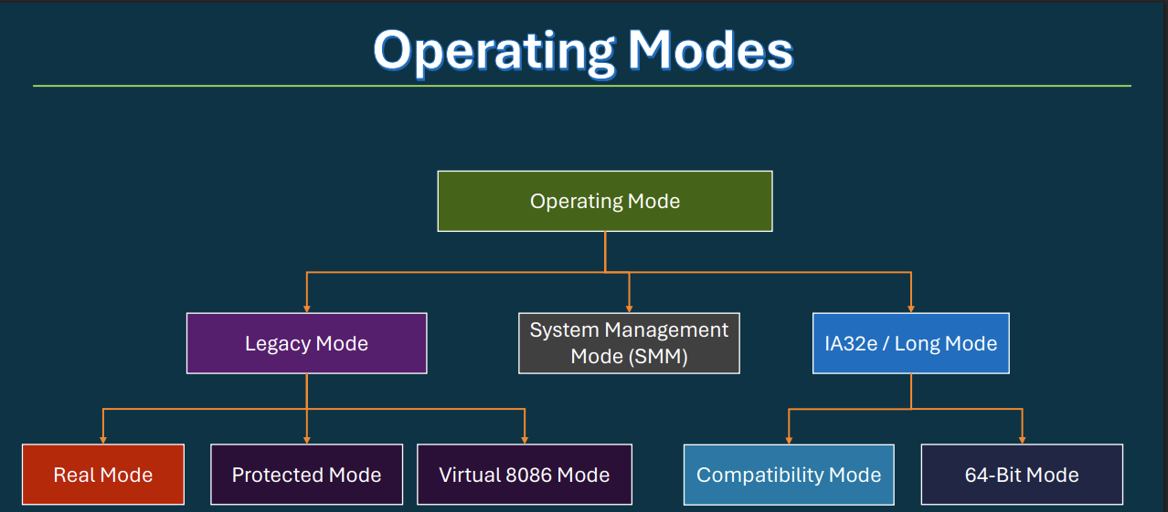
CPU Operating Modes
The CPU transitions through different hardware states that dictate memory addressing limits and security ring enforcement.
1. Legacy Mode (The 32-Bit & 16-Bit Era)
This branch represents the older architecture styles before AMD64 took over.
Real Mode (CPU Reset)
The Architecture : When the CPU first powers on, it starts here. It is a 16-bit environment with a maximum of 1MB of addressable memory.
The Maldev Context : There is zero security. There are no privilege rings (Ring 0 and Ring 3 do not exist), no memory protections, and no paging. Every program has raw, direct access to the hardware. Advanced bootkits (like BlackLotus) target the boot sequence here or early UEFI phases to compromise the system before the OS or EDR ever loads.
Protected Mode
The Architecture : The jump to 32-bit. This is where modern operating system concepts were born. It introduced Virtual Memory (Paging) and hardware-enforced privilege rings (Ring 0 for Kernel, Ring 3 for User-land).
The Maldev Context : If you write a 32-bit exploit, you are dealing with Protected Mode. Memory is segmented and protected. You cannot just read another program’s memory without passing through the kernel (using APIs like ReadProcessMemory), which EDRs hook and monitor.
Virtual 8086 Mode
The Architecture : A hardware sandbox inside Protected Mode designed to run legacy 16-bit DOS applications safely without crashing the 32-bit OS.
The Maldev Context : Mostly a historical artifact today, but in the past, hackers used to find vulnerabilities here to execute “VM Escapes,” breaking out of the 16-bit sandbox to gain Ring 0 execution in the 32-bit host.
2. IA32e / Long Mode (The Modern 64-Bit Kingdom)
64-Bit Mode (Focus of the course)
The Architecture : The native 64-bit environment. It utilizes massive registers (RAX, RBX) and a massive flat memory address space.
The Maldev Context : Security is brutal here. Microsoft introduced Kernel Patch Protection (PatchGuard), SMEP, and SMAP to prevent you from easily hooking the kernel. You have to rely on advanced BYOVD (Bring Your Own Vulnerable Driver) attacks to disable telemetry, because you can no longer just overwrite kernel structures directly like you could in 32-bit Protected Mode.
Compatibility Mode
The Architecture : This is how a 64-bit Windows OS runs older 32-bit applications. Windows uses a subsystem called WoW64 (Windows 32-bit on Windows 64-bit) to translate 32-bit API calls into 64-bit system calls under the hood.
The Maldev Context : This is an elite attack surface. EDRs often place their detection hooks in the 32-bit memory space of a WoW64 process. Exploit developers use a technique called Heaven’s Gate to manually force the CPU to switch from Compatibility Mode into 64-Bit Mode mid-execution. By doing this, the malware completely steps over the EDR’s 32-bit hooks, executing raw 64-bit syscalls completely undetected.
3. System Management Mode (SMM)
The Architecture : Often referred to as “Ring -2”. It is a special, highly privileged operating mode used by the hardware firmware (BIOS/UEFI) to handle hardware control like thermal management or power states.
The Maldev Context : SMM execution is completely invisible to the operating system, the hypervisor, and the EDR. If an APT or state-sponsored group manages to write a rootkit into SMM, they have “God Mode.” The OS cannot audit it, and the malware survives complete hard drive wipes and OS reinstallations.
NASM vs. MASM
While both assemblers use Intel syntax (mov destination, source), they process variables, memory references, and directives entirely differently.
1. Memory Dereferencing (The Bracket Rule)
NASM: Brackets []always mean “read/write the data at this memory address.” Without brackets, it always means the immediate address pointer.
MASM: Brackets are ambiguous and often optional. MASM tracks variable types internally and infers memory access.
; --- NASM Syntax ---mov rax, my_var ; Moves the ADDRESS (pointer) of my_var into RAXmov rax, [my_var] ; Moves the DATA stored inside my_var into RAX; --- MASM Syntax ---mov rax, OFFSET my_var ; Requires 'OFFSET' to get the ADDRESSmov rax, my_var ; Moves the DATA stored inside (brackets optional)
2. Variable Definitions
NASM: Labels are defined with the data allocation allocation size (db, dw, dd, dq) placed after the label name. Case-sensitive.
MASM: Data allocations (DB, DWORD, QWORD) are placed between the variable name and the value. Case-insensitive.
; --- NASM ---msg db "Hello World", 0val dq 0x1122334455667788; --- MASM ---msg DB "Hello World", 0val QWORD 01122334455667788h ; Note the trailing 'h' for hex in MASM
3. High-Level Constructs & Macros
NASM: Pure, bare-metal assembly. It does not support high-level programming logic loops natively. You must manually construct loops and branches using loops (cmp, jmp, conditional jumps like je, jne).
MASM: Includes built-in high-level compiler directives that mimic C logic, allowing for faster structured coding.
NASM (-f bin): The absolute king for crafting position-independent shellcode. It can output completely raw, flat binary blobs without adding standard OS headers (PE/ELF), which you can feed directly into memory allocation loaders.
MASM (ml64.exe): Designed to link smoothly with the Microsoft C/C++ compiler (cl.exe). If you want to embed custom standalone assembly procedures natively inside a Visual Studio C++ project, MASM is seamless.
The Low-Level Execution Pipeline: From Code to RAM
When writing assembly or low-level exploit code, you are dealing directly with the bare metal. To turn plain text into bytes executing on a physical CPU, your code must pass through this exact four-stage automated pipeline.
1. The Compiler (The Architect)
What it does: Translates high-level language (like C or C++) into low-level CPU assembly language.
Why it matters: The hardware cannot process abstract logic like if (x == 5). The compiler translates this logic into the hardware’s specific instruction set architecture (ISA).
Output: Assembly Source File (.asm or .s).
Example: Translates int x = 5; into mov eax, 5.
2. The Assembler (The Translator)
What it does: Translates assembly mnemonics (text instructions) into raw binary machine code bytes (opcodes). This is where tools like NASM or MASM operate.
Why it matters: The CPU doesn’t understand words like mov or push. It only executes raw binary bytes (hex representation). The assembler parses your instruction text, maps it to the CPU’s opcode matrix, and writes the bytes out.
Output: Object File (.obj on Windows, .o on Linux).
Crucial Note: An object file contains raw machine code but is not runnable. It lacks an execution header, OS-level structure, and resolved external memory references.
3. The Linker (The Construction Crew)
What it does: Collects multiple object files, merges them, resolves external function references, and packages the entire bundle into a structure the OS recognizes.
Why it matters: If your code calls a Windows API (like MessageBoxA or VirtualAlloc), your object file only has an empty placeholder. The linker looks up the OS import libraries (.lib), links your placeholders to the actual DLL exports, and adds the OS executable structure (the Portable Executable / PE Header).
Output: Executable File (.exe or .dll).
4. The Loader (The Gatekeeper)
What it does: A built-in OS kernel component that reads the executable from disk, carves out a virtual memory address space (RAM), loads the segments, and points the CPU to the entry point.
Why it matters: Executables must reside in physical/virtual memory to run. The loader parses the PE header, maps the code/data sections with explicit memory protections (Read, Write, Execute / RX, RW), performs necessary base relocations, and points the CPU’s Instruction Pointer register (RIP/EIP) directly to your program’s entry point.
Data Types & Little-Endian Memory Layout
When writing custom shellcode, understanding how the CPU stores variables in RAM is mandatory to prevent access violations.
The Mapping:
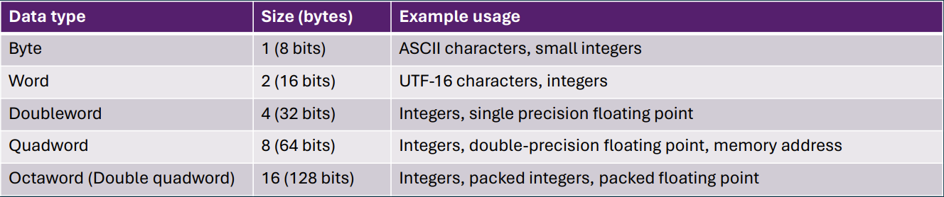
Byte = 8 bits (char in C, db in ASM)
Word = 16 bits (short in C, dw in ASM)
Dword = 32 bits (int in C, dd in ASM)
Qword = 64 bits (long long in C, dq in ASM)
The Offensive Context (Little-Endian): x64 architecture stores data with the Least Significant Byte (LSB) at the lowest memory address. If you need to push the DWORD 0x11223344 onto the stack for an API call, it physically sits in memory as 44 33 22 11. If you fail to reverse your bytes when writing raw opcodes, your API arguments will be garbage and the thread will crash.
The Core Data Types (MASM)
Byte (8-bit): Used for single ASCII characters or small opcodes. Hex: 0xFF
Word (16-bit): Used for UTF-16 characters or short offsets. Hex: 0xFFFF
Dword (32-bit): The standard 32-bit integer. Hex: 0xFFFFFFFF
Qword (64-bit): Used for 64-bit memory addresses and pointers. Hex: 0xFFFFFFFFFFFFFFFF
The Two’s Complement Vulnerability
Memory holds bits, not intent. The hex value 0xFFFFFFFF in a 32-bit register translates to:
4,294,967,295 if read by an unsigned instruction.
-1 if read by a signed instruction (because the highest bit is set to 1).
The Exploit: Attackers pass massive hex values (like 0xFFFFFFFF) into bounds-checking functions. If the developer used a signed integer check, the system reads it as -1 (passing the check). When passed to memory allocation APIs that expect unsigned integers, it results in massive allocations and heap corruption.
Hexadecimal & Memory Addressing
Base 16 (Hex) is mandatory for exploit development because exactly two hex characters equal one byte of memory. All memory offsets, shellcode arrays, and pointer arithmetic must be calculated in Hex to ensure alignment.
Register Aliasing & Null-Byte Evasion
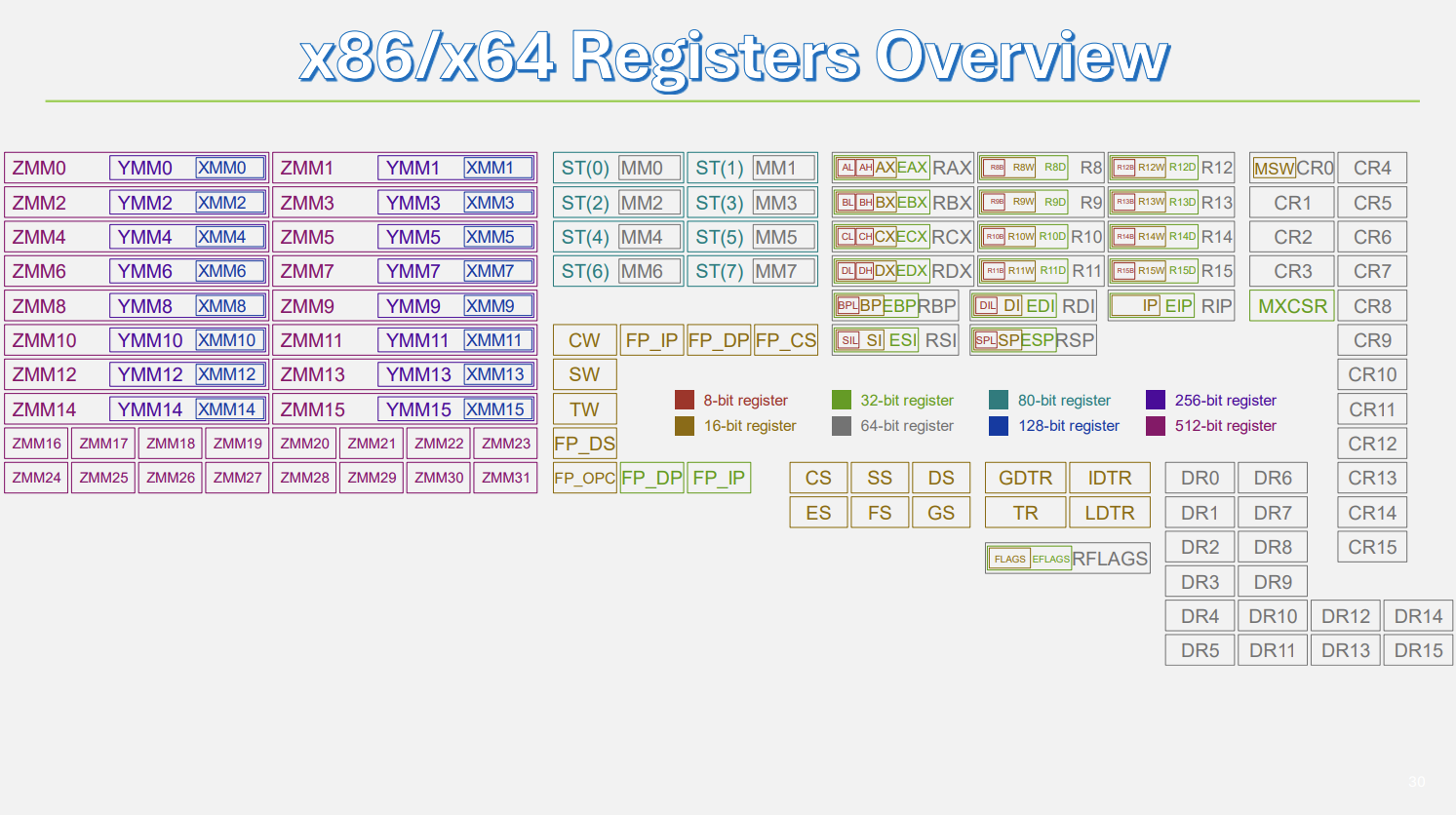
General Purpose Registers (like RAX) are 64-bit containers, but they are sliced into smaller, directly accessible sub-registers (EAX, AX, AH, AL).
The Offensive Context: This slicing is the primary mechanism for writing position-independent shellcode that avoids null-byte (0x00) restrictions.
The Trap: Compiling mov rax, 0x5 generates the opcodes 48 c7 c0 05 00 00 00. String-copy vulnerabilities will terminate execution the moment they hit those zeros.
The Solution: Zero the register first with xor rax, rax, then write only to the 8-bit sub-register: mov al, 0x5. This generates b0 05 clean, tiny, and zero null bytes.
x64 Architecture Registers
In low-level engineering, hardware registers are your absolute source of truth. Using the wrong register doesn’t just throw a compiler warning; it causes an access violation and crashes the thread.
1. The Core Volatile Registers (x64 Calling Convention)
If you are building a custom loader and calling Windows APIs (like VirtualAlloc or CreateThread), the hardware strictly enforces where your arguments go.
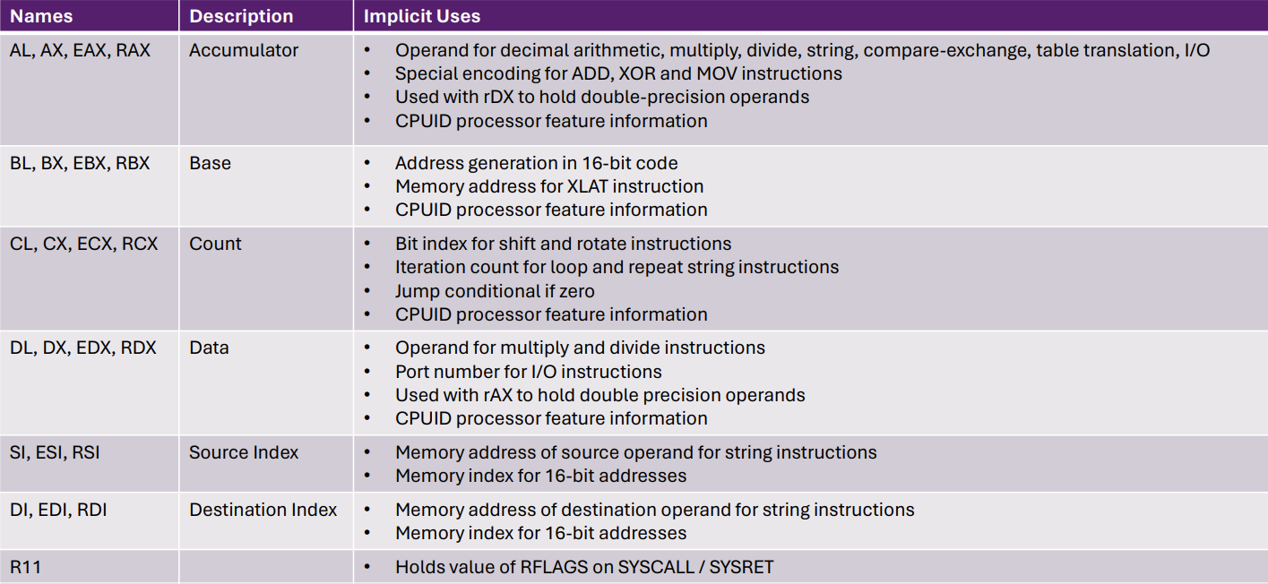
RCX, RDX, R8, R9: These handle arguments 1 through 4. Any additional arguments get pushed to the stack. If you misalign these, the kernel drops the execution.
RAX (The Accumulator): The scratchpad. Most importantly, when a Windows API finishes executing, it always drops its return value (like a new memory address or an error code) right here.
2. The Execution Pointers
These registers control the thread’s memory state and execution flow. Hijacking these is the core of exploit development.
RIP (Instruction Pointer): Points to the exact memory address of the next executing opcode. In shellcode, you never hardcode memory addresses. You use RIP-relative addressing to dynamically locate your variables, making your payload 100% Position Independent.
RSP (Stack Pointer): Points to the current top of the stack. If an EDR blocks standard execution, you overwrite the stack and manipulate RSP to force the CPU to bounce between existing, legitimate memory addresses (Return-Oriented Programming / ROP).
RBP (Base Pointer): Traditionally used to set up local stack frames for variables, but modern optimized C compilers often just use it as another general storage register.
3. Index & General Storage
RSI & RDI (Source & Destination Index): The heavy lifters for raw memory manipulation. If your loader is decrypting a payload and moving it into a new memory segment, you use these registers with string instructions to blast bytes from point A to point B rapidly.
RBX, R10 - R15: General storage. These are often “non-volatile,” meaning if a function uses them, it is required to save their original values to the stack and restore them before returning.
4. Specialized Hardware
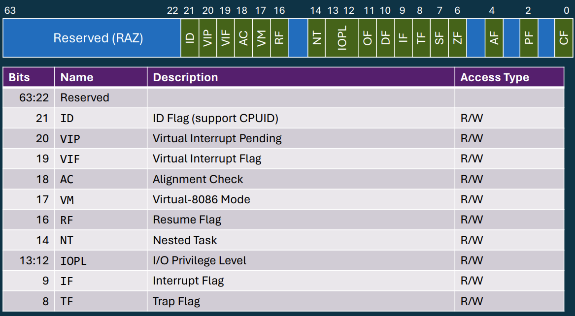
RFLAGS: Stores the mathematical state of the CPU (Zero Flag, Carry Flag, Sign Flag). When you write an if statement or a loop in C, the compiler translates it into a cmp instruction that updates RFLAGS, followed by a conditional jump (je, jne) that reads those flags.
XMM / YMM (SIMD Registers): The massive 128-bit and 256-bit data containers. Red teamers hijack these specifically for rapid, stealthy payload encryption/decryption in memory, bypassing standard Windows cryptographic APIs.
RFLAGS
The RFLAGS register controls conditional branching and hardware-level execution states. Understanding how to manipulate these bits is mandatory for binary patching, reverse engineering, and anti-analysis tradecraft.
1. Conditional Branching Flags
These flags are dynamically updated after arithmetic or comparison (cmp, test) instructions.
Zero Flag (ZF): Set to 1 if the result of an operation is exactly zero. This is the primary target for binary instrumentation. By flipping ZF in a debugger at runtime, an analyst can invert the outcome of authorization checks or EDR telemetry branches (e.g., forcing a jne to act like a je).
Sign Flag (SF): Set to 1 if the result of an operation is negative. Used heavily in loop decrements.
Carry Flag (CF): Set to 1 if an operation results in an overflow of the destination register’s physical bit capacity. Frequently manipulated in custom, bitwise shellcode encryption routines (shifts/rotates).
2. Hardware Control Flags
These flags directly alter how the CPU processes instructions.
Direction Flag (DF): Dictates the memory traversal direction for high-speed string operations (movsb, stosb).
cld sets DF to 0 (Increment/Forward).
std sets DF to 1 (Decrement/Backward).
Maldev Rule: Always execute cld before writing payloads into memory via assembly. Failing to do so can result in backwards memory corruption if the thread inherited a dirty flag state.
Trap Flag (TF): The hardware debugging flag. When set to 1, the CPU fires an INT 1 exception after every single opcode execution. Used maliciously by rootkits and loaders to detect the presence of Ring-3 debuggers (x64dbg) or Ring-0 kernel debuggers (WinDbg).
Sign vs. Zero Extension
When a compiler casts a smaller data type (like an 8-bit char) into a larger one (like a 32-bit int), the CPU must fill the newly created empty bits. The compiler’s choice of instruction dictates how the raw memory is interpreted.
Zero Extension (movzx)
Used when the source variable is defined as unsigned. The CPU pads the new empty space on the left entirely with zeros.
0xFF (255) becomes 0x000000FF (255).
Sign Extension (movsx)
Used when the source variable is defined as signed. To prevent a negative number from being corrupted into a massive positive number, the CPU copies the Most Significant Bit (the leftmost sign bit) across all the new empty space.
0xFF (-1) becomes 0xFFFFFFFF (-1).
Instruction Operands Cheat Sheet
Operands specify where an assembly instruction retrieves or stores its data.
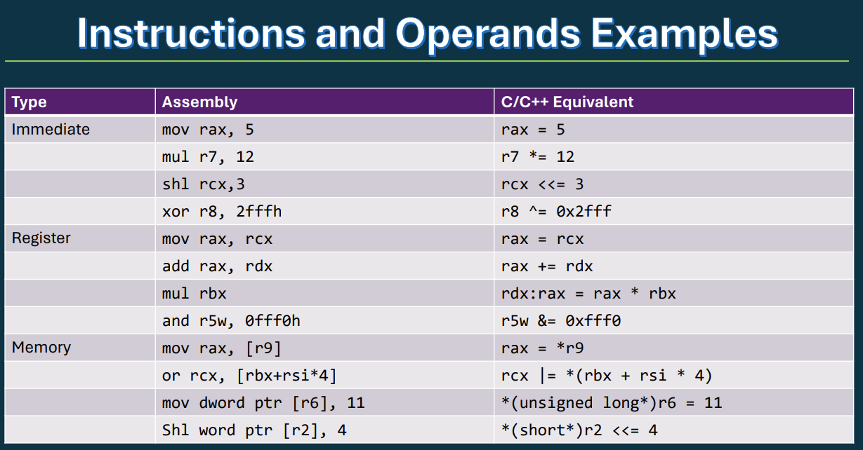
The Three Operand Targets
Immediate: Hardcoded value embedded directly within the instruction bytes (e.g., mov rax, 0x20). Max execution speed.
Register: Data stored inside the CPU’s on-silicon storage cells (e.g., mov rax, rcx). High-speed execution.
Memory: Data stored in system RAM, denoted by brackets [] (e.g., mov rax, [rbx]). Acts as a pointer dereference (*ptr). Requires a bus transaction to fetch.
SIB Addressing Math
The syntax [base + index * scale] allows real-time calculation of array offsets at the hardware level.
Example:[rbx + rsi * 8] translates to: Start at base address RBX, skip forward RSI elements, where each element is 8 bytes wide (a 64-bit pointer or QWORD).
Pointer Size Enforcement
When moving data from an immediate value into a memory address, the destination size must be explicitly declared to avoid ambiguity:
byte ptr [rax]→ 1 Byte (8 bits)
word ptr [rax]→ 2 Bytes (16 bits)
dword ptr [rax]→ 4 Bytes (32 bits / DWORD)
qword ptr [rax]→ 8 Bytes (64 bits / QWORD)
The MOV Instruction Family & Data Movement
In x86/x64 assembly, moving data is not as simple as an assignment operator (=). The CPU utilizes distinct instructions and physical pathways depending on the size, location, and endianness of the data being moved.
Core Rules & Constraints
Memory-to-Memory Restriction: The CPU cannot move data directly from one RAM address to another RAM address in a single instruction (e.g., mov [rax], [rbx] is illegal). A general-purpose register must always act as the intermediary.
64-Bit Immediate Exception:MOV is the only instruction capable of loading a literal, hardcoded 64-bit value directly into a register (e.g., loading a full 8-byte virtual memory address).
Size Matching: The source and destination operands must be identical in size unless an explicit extension instruction is used.
Extended MOV Variations
MOVZX (Move with Zero Extension): Copies a smaller unsigned value into a larger register, padding the upper bits with 0s.
MOVSX / MOVSXD (Move with Sign Extension): Copies a smaller signed value into a larger register, copying the Most Significant Bit (sign bit) across the upper bits to preserve negative numbers. MOVSXD specifically targets a 32-bit source moving into a 64-bit destination.
MOVBE (Move Big Endian): Moves data while simultaneously reversing the byte order.
MOVD / MOVQ (Move Doubleword/Quadword to/from XMM): Moves 32-bit or 64-bit data between standard general-purpose registers and 128-bit vector/SIMD registers (XMM).
The Offensive Engineering Context
Network Order Realignment (MOVBE): While x64 processors operate using Little Endian, network protocols require Big Endian (Network Byte Order). Instead of parsing complex bit-shifting math functions in C to align a port or IP structure for a socket connection, offensive operators use MOVBE to reverse data on the fly.
Register Evasion (MOVD / MOVQ): Memory scanners, AV, and EDR solutions frequently monitor general-purpose registers (RAX, RBX, etc.) during execution to catch plaintext strings or decryption keys. Vector registers (XMM) are often ignored by legacy or performance-constrained hooks. Staging payloads or multi-byte cryptographic keys inside XMM registers via MOVQ hides them from basic inspection.
ADD, SUB, and Flag Mechanics Cheat Sheet
ADD and SUB alter the destination register directly and dynamically update the system’s status flags based on the resulting mathematical state.
Immediate Value Sign-Extension
Arithmetic operations cannot accept raw 64-bit immediate values. If the destination is a 64-bit register, a 32-bit immediate value is automatically sign-extended by the processor before execution.
Hardcoded 5 becomes 0x0000000000000005
Hardcoded -5 becomes 0xFFFFFFFFFFFFFFFB
Multi-Register Arithmetic Chain
To perform math on data structures wider than 64 bits (such as cryptographic payloads):
ADC (Add with Carry):Dest = Dest + Source + CarryFlag
SBB (Subtract with Borrow):Dest = Dest - Source - CarryFlag
Key Status Flags Affected
Zero Flag (ZF): Automatically set to 1 if the result of the operation is exactly 0. Frequently targeted by conditional jumps (JE/JNE) in control-flow flattening obfuscation.
Carry Flag (CF): Set to 1 if an unsigned operation overflows (in ADD) or requires a borrow (in SUB).
CALL & RET
The CPU does not inherently understand “functions.” It relies entirely on the Stack and the Instruction Pointer (RIP) to branch execution and find its way back.
The Core Mechanics
CALL <address>: Executes two hardware steps in a single cycle:
Pushes the address of the next sequential instruction (the return address) onto the top of the stack.
Overwrites the RIP register with the target <address>, forcing execution to jump there.
RET (Return): The exit strategy.
Pops the 64-bit value sitting at the top of the stack ([RSP]) directly into the RIP register.
Execution instantly snaps back to the restored address.
RET [value] (e.g., ret 8): Pops the return address, then immediately adds [value] to the Stack Pointer (RSP). Used in specific calling conventions to automatically clean up function arguments from the stack without requiring extra instructions.
Args 5+ (Overflow): Pushed onto the stack from right to left. They reside directly above the shadow space.
C++ Class Context: The implicit this pointer for structural object objects always takes priority in RCX.
Stack Preservation Boundaries
Shadow Space: A mandatory 32-byte management block allocated by the caller immediately before execution, reserved strictly for the API’s internal register spills.
Volatile Registers (Unsafe across calls):RAX, RCX, RDX, R8-R11. Can be altered at any time by the invoked function.
Non-Volatile Registers (Safe/Must Preserve):RBX, RBP, RSI, RDI, R12-R15. Must be pushed to the stack and popped back if modified within custom procedures.
Bitwise Instructions
Bitwise operators manipulate data at the raw electrical level. While standard developers use them for low-level math, offensive engineers use them constantly for evasion, obfuscation, and shellcode optimization.
The Core Logic Gates
XOR (Exclusive OR - The Reversible Cipher): The undisputed king of malware instructions.
Register Clearing:xor rax, rax zeroes out a register instantly (A XOR A = 0). It takes fewer bytes than a MOV instruction and contains zero null characters (0x00), making it perfectly safe for buffer overflow shellcode.
Payload Encryption: XOR is completely reversible. Malware uses it to encrypt shellcode to bypass static signatures. When the loader executes, it simply XORs the memory a second time with the exact same key to restore the original payload.
AND (The Mask & Aligner): Outputs a 1 only if both input bits are 1.
Stack Alignment: Used to forcefully align memory pointers. Executing and rsp, 0xFFFFFFFFFFFFFFF0 violently strips away the last 4 bits of the address, snapping the stack pointer directly onto the nearest 16-byte boundary to prevent API execution crashes.
OR (The Flag Combiner): Outputs a 1 if either input bit is 1.
API Configuration: Used to stack multiple independent settings into a single register. When you see MEM_COMMIT | MEM_RESERVE in C++, the compiler translates that | into an OR instruction to combine the bits.
NOT (The Bit Flipper): Inverts every bit (1s become 0s, 0s become 1s). Used as a fast, lightweight obfuscation technique (1’s complement cipher) to hide strings, domain names, or payload configurations from static memory scanners.
Shifts & Rotates
A CPU register is an 8-slot conveyor belt. Shifts push bits off the edge into the void (destructive), while Rotates bend the conveyor belt into a continuous loop (preservative).
Shifts: The Stealth Math Hack
Used to multiply or divide without using the slow, easily detectable MUL or DIV instructions.
SHL (Shift Left): Multiplies by 2. Fills the empty right slot with a 0.
SHR (Logical Shift Right): Divides by 2 (Unsigned). Fills the empty left slot with a 0. Warning: Destroys negative numbers by overwriting the sign bit.
SAR (Arithmetic Shift Right): Divides by 2 (Signed). Safely preserves negative numbers by duplicating the Most Significant Bit (MSB) into the empty slot.
Rotates: The Cryptographic Loop
Used in malware to obfuscate strings, hide configurations, and build custom API hashes (like the famous ROR 13 technique). No data is ever lost.
ROL / ROR (Rotate Left/Right): The bit that falls off the edge instantly teleports to the empty slot on the opposite side.
RCL / RCR (Rotate through Carry): Includes the Carry Flag as a physical 9th seat in the loop.
The Carry Flag (CF)
Whenever a bit falls off the edge during any shift or rotate, a copy of it is caught in the Carry Flag. Offensive engineers use conditional jumps (like JC - Jump if Carry) to alter execution flow based on the bit that just dropped.
Assembly Floating Point (MASM) Cheat Sheet
MASM Data Types
real4 (32-bit): Equivalent to C/C++ float. Takes up 4 bytes of memory.
real8 (64-bit): Equivalent to C/C++ double. Takes up 8 bytes of memory. Used for high-precision math.
real10 (80-bit): Legacy extended precision. Used internally by the old x87 FPU hardware.
Hardware Execution
Floating point math is not done in RAX, RCX, or standard general-purpose registers. It uses a dedicated hardware unit and the 128-bit XMM Vector Registers. You cannot use standard ADD or SUB instructions; you must use dedicated SSE instructions like ADDSS (Add Scalar Single-Precision) or MOVSS (Move Scalar Single-Precision).
CPU Decision Making (Jumps & The RFLAGS Dashboard)
The CPU does not understand if, while, or for loops. It makes all execution decisions through a strict two-step mechanical process: perform an operation to flip hardware switches, then jump based on those switches.
Step 1: Setting the Flags
Arithmetic (ADD, SUB) and bitwise operations (XOR, AND) automatically update the RFLAGS register based on their result.
Zero Flag (ZF): Trips to 1 if the math result is exactly zero.
Carry Flag (CF): Trips to 1 if a bit falls off the edge (unsigned overflow/borrow).
Sign Flag (SF): Trips to 1 if the result is negative.
Overflow Flag (OF): Trips to 1 if signed math is corrupted.
Step 2: The Conditional Jump (Jcc)
Jump instructions look strictly at the RFLAGS dashboard. If the required switch is flipped, they hijack the Instruction Pointer (RIP) to a new address. If not, they do nothing.
JZ / JNZ: Jump if Zero / Jump if Not Zero (Checks ZF).
JC / JNC: Jump if Carry / Jump if Not Carry (Checks CF).
The MOV Trap
MOV instructions never touch the RFLAGS dashboard. > Executing mov rax, 0 followed by jz payload is a fatal error. The JZ instruction will read whatever garbage was left on the dashboard from a previous instruction. You must use an instruction that trips the flags, like xor rax, rax or test rax, rax, before attempting to branch.
x64 Memory Pointer Sizes
RAM has no natural borders. A memory address (like [r8]) only tells the CPU where to start standing. The size label tells the CPU how far to reach out its hands.
byte ptr (1 Box) ➔ Grabs 1 byte (Fits an 8-bit register like al)
word ptr (2 Boxes) ➔ Grabs 2 bytes (Fits a 16-bit register like ax)
dword ptr (4 Boxes) ➔ Grabs 4 bytes (Fits a 32-bit register like eax)
qword ptr (8 Boxes) ➔ Grabs 8 bytes (Fits a 64-bit register like rax)
The Pointer Trap dword ptr to try and grab a single 1-byte letter, the CPU will blindly rip out 4 memory boxes at once. You will grab the letter you wanted, plus the next 3 bytes of adjacent memory, corrupting your register.
If you use a
MASM Sections & Data Types Reference
Every section tells the Windows Loader what memory permissions to apply when the .exe is loaded into RAM. MASM automatically consolidates multiple identical sections during compilation.
PE Sections Map:
.code (Execute/Read): Your Assembly instructions. Maps to the .text section (RX).
.data (Read/Write): Initialized global variables (e.g., db 1,2,3). Maps to the .data section (RW).
.data? (Read/Write): Uninitialized variables (e.g., myvalue db ?). Maps to the .bss section (RW). Dev tip: Reserving massive arrays here keeps your .exe file size tiny on disk, but inflates it in RAM.
.const (Read Only): Constants like your XOR key or strings. Maps to the .rdata section (R).
MASM Data Sizes:
Directive
C Equivalent
Size
Example
db (Define Byte)
char
1 Byte
db 1,2,3,4
dw (Define Word)
short
2 Bytes
dw 1000h
dd (Define Dword)
int
4 Bytes
Count dd 12345678h
dq (Define Qword)
long long
8 Bytes
C dq 299792458
real4
float
4 Bytes
pi real4 3.1415926
LEA (Load Effective Address) vs. MOV
LEA is the Assembly equivalent of the C & (address-of) operator.
MOV RAX, [1000]: Dereferences memory. Fetches the data stored inside address 1000.
LEA RAX, [1000]: Does NOT touch memory. Simply loads the number 1000 into RAX.
The Math Trick:
Because LEA leverages the CPU’s memory-address calculation hardware but stops before actually reading RAM, it is heavily used for fast, single-line math operations.
Example: lea rax, [rbx + rcx*2 + 8] will instantly do the math and store the result in RAX without triggering an access violation, even if that address doesn’t exist.
x64 Addressing Modes Cheat Sheet
An addressing mode is simply the formula the CPU uses to calculate where to read or write data.
1. Register (No RAM)
Syntax:mov rax, rcx
How it works: Data moves directly between CPU silicon. Fastest execution. Both registers must be the exact same size.
2. Register Indirect (The Pointer)
Syntax:mov [rax], ebx
How it works: The register holds a memory address. The brackets [ ] tell the CPU to dereference it and go to that location in RAM.
3. Indirect + Offset (The Struct/Stack)
Syntax:mov [rax + 0x10], cx
How it works: Goes to the address in the register, then walks a fixed number of bytes forward/backward. Heavily used to access local stack variables or specific fields inside a C struct.
4. Scaled Indexed / SIB (The Master Formula)
Syntax:mov [rax + rsi * 4 + 0x20], edx
How it works:Base + (Index * Scale) + Displacement. The ultimate calculator for arrays. (e.g., Start at array base, jump to the 3rd index, multiply by 4 because integers are 4-bytes large).
5. RIP-Relative (Position Independent Code)
Syntax:lea rax, [rip + 0x09]
How it works: Calculates a memory location relative to the currently executing instruction (RIP).
The Hacker Trick: This is mandatory for writing Position Independent shellcode. It ensures your payload still finds its variables no matter where Windows ASLR decides to load your binary in memory.
x64 Stack Essentials: PUSH, POP, and Memory
The stack is a memory block managed as a Last-In-First-Out (LIFO) data structure. On x86/x64 architectures, the stack grows downwards in memory.
1. The RSP Register (Stack Pointer)
The current stack pointer is managed by the RSP register.
It always points to the top of the stack (the lowest memory address where the last valid value was stored).
CALL and RET instructions always use the stack behind the scenes to track return addresses.
2. The PUSH Instruction
The PUSH instruction pushes a value onto the top of the stack.
Supported Operands:
PUSH register (16-bit or 64-bit)
PUSH memory (16-bit or 64-bit)
PUSH constant (16-bit or 32-bit)
Key Rules:
A 32-bit constant is automatically sign-extended to 64-bit.
It is best to avoid 16-bit PUSH operations.
Always keep the stack 8-byte aligned (or 16-byte aligned for Windows API calls).
Operation Steps:
Decrements RSP by the size of the operand (usually 8 bytes).
Copies the value to the memory pointed to by the new RSP address.
3. The POP Instruction
The POP instruction gets a data item off the stack.
Supported Operands:
POP register (16-bit or 64-bit)
POP memory (16-bit or 64-bit)
Operation Steps:
Value from the current [RSP] address is copied to the operand.
RSP is incremented by the operand size (usually 8 bytes, moving the pointer back “up”).
4. Visualizing the Memory Mechanics
Here is exactly what happens in memory when executing a PUSH RAX, moving the RSP pointer from 0x1230 down to 0x1228.
graph TD
    classDef pointer fill:#b52a2a,stroke:#fff,stroke-width:2px,color:#fff;
    classDef mem fill:#2d2d2d,stroke:#777,stroke-width:1px,color:#ddd;
    classDef newmem fill:#005a9e,stroke:#fff,stroke-width:2px,color:#fff;

    High[High Memory]:::mem --> A[0x1240: Item a]:::mem
    A --> B[0x1238: Item b]:::mem
    B --> C[0x1230: Item c]:::mem

    C -.->|RSP BEFORE PUSH| RSP1((RSP = 0x1230)):::pointer

    C -->|Subtract 8 bytes| D[0x1228: Pushed Value / RAX]:::newmem

    D -.->|RSP AFTER PUSH RAX| RSP2((RSP = 0x1228)):::pointer
    D --> Low[Low Memory]:::mem
5. CPU Order of Operations (PUSH vs. POP)
sequenceDiagram
    participant CPU
    participant RSP as RSP (Stack Pointer)
    participant RAM as Stack Memory

    Note over CPU, RAM:  Instruction: PUSH RAX
    CPU->>RSP: 1. Decrement by size of operand (e.g., 8 bytes)
    CPU->>RAM: 2. Copy value to memory pointed to by RSP

    Note over CPU, RAM:  Instruction: POP RBX
    CPU->>RAM: 1. Copy top-of-stack value into operand
    CPU->>RSP: 2. Increment by size of operand (e.g., 8 bytes)
    Note right of RAM:  OPSEC WARNING: The popped value is STILL in memory!
Windows x64 Stack Alignment ( sub rsp, X)
The Hardware Rule: The stack MUST be perfectly 16-byte aligned right before executing a call instruction. Because the CPU pushed an 8-byte Return Address to enter your function, the stack starts off misaligned. To balance it, the final amount of space you subtract from RSP must ALWAYS be an ODD multiple of 8.
1. The Tax (Shadow Space)
If your function calls any other function or Windows API, you must unconditionally reserve 32 bytes (0x20) for the callee’s register spill space.
2. The Luggage (Local Variables)
Tally the size of the variables you need to store inside your function:
int / DWORD = 4 bytes
void* / HANDLE / Pointers = 8 bytes
Action: Round your total variable size up to the nearest multiple of 8.
3. The Math (The Odd 8s Check)
Calculate your Base Number = Tax + Luggage. Then, divide that number by 8.
If the result is ODD (1, 3, 5, 7…):
You are perfectly aligned. Keep this number!
(Example: 32 Tax + 8 Luggage = 40. → 40 / 8 = 5. Use sub rsp, 40)
If the result is EVEN (2, 4, 6, 8…):
Your stack is misaligned and the API will crash. Add 8 bytes of dummy padding to fix the balance.
(Example: 32 Tax + 16 Luggage = 48. → 48 / 8 = 6. Add 8. Use sub rsp, 56)
Luggage only counts things that belong to your function. Arguments you are sending to someone else do not belong to you.
Hex Numbers Operations (Add,Sub)
The Golden Rule: Normal math uses Base-10 (0-9). Hex uses Base-16 (0-F).
A=10 | B=11 | C=12 | D=13 | E=14 | F=15
When you carry in addition, you roll over at 16 (not 10).
When you borrow in subtraction, you borrow 16 (not 10).